Design, manufacturing and performance study of a 10mm brushless coreless motor
Addressing the core requirements of high response, high efficiency, and low vibration in the field of micro-precision drives, our company focuses on a 10mm diameter brushless coreless motor, conducting research across the entire chain of electromagnetic design, structural optimization, manufacturing processes, and control strategies. By eliminating cogging effects through a coreless rotor structure and combining neodymium iron boron permanent magnets with precision winding technology, we achieve low moment of inertia and high torque density characteristics. A three-dimensional electromagnetic simulation model was established based on ANSYS Maxwell to analyze the air gap magnetic field, torque output, and temperature rise, and a prototype was fabricated for performance testing. Results show that the designed 10mm brushless coreless motor achieves an energy conversion efficiency of 75%–85%, reduces moment of inertia by approximately 90% compared to traditional iron-core motors, and controls torque fluctuations within 2%. This meets the application requirements of robot joints, precision medical equipment, and portable drones, providing technical support for the engineering application of micro-brushless motors.
Brushless Coreless Motor; 10mm Micro Motor; Electromagnetic Design; Coreless Rotor; Precision Control
With the rapid development of micro-robotics, minimally invasive medical devices, and precision components in consumer electronics, micro-drive components are showing a trend towards lightweight, high-response, and high-precision designs. Traditional brushed micro-motors suffer from drawbacks such as brush wear, short lifespan, and high noise, making it difficult to meet the long-term stable operation requirements of high-precision applications. Conventional brushless coreless motors, limited by cogging effect and high rotational inertia, exhibit significant shortcomings in dynamic response and operational smoothness.
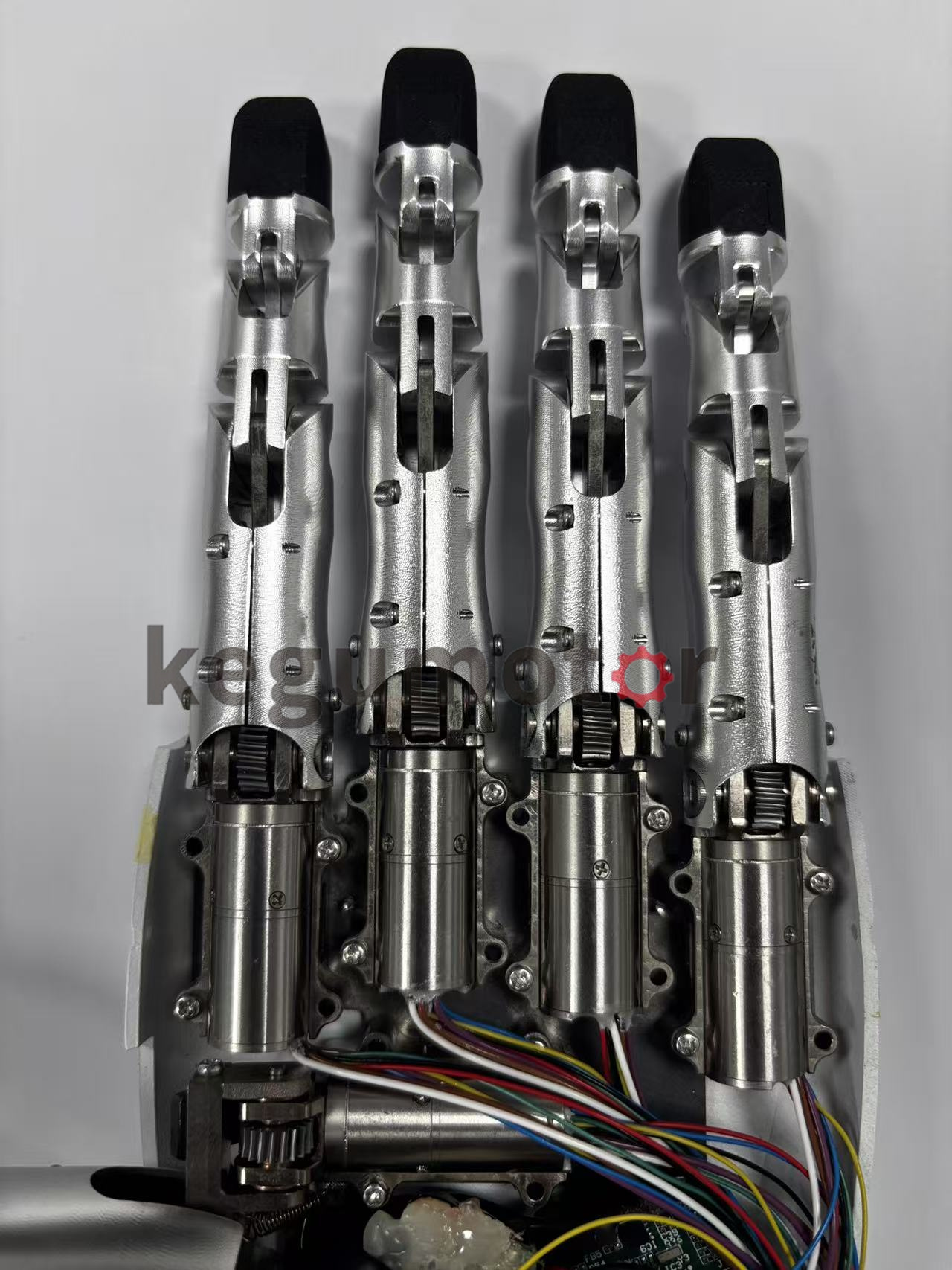
Brushless coreless motors, with their coreless self-supporting hollow cup windings as the core structure, completely eliminate cogging effect while significantly reducing rotor rotational inertia, combining the long lifespan of brushless motors with the high-response characteristics of a hollow cup structure. Among them, the 10mm micro brushless coreless motor, due to its compact size and strong adaptability, has become a core drive component for applications such as robot dexterity hands, endoscope drives, portable gimbals, and attitude control of micro-drones. This research focuses on the design, manufacturing, and performance optimization of a 10mm brushless coreless motor. Through electromagnetic simulation and experimental verification, a complete technical solution is constructed to provide theoretical and practical support for its engineering application.
II. Structural Principle of the 10mm Brushless Coreless Motor
2.1 Core Structural Components
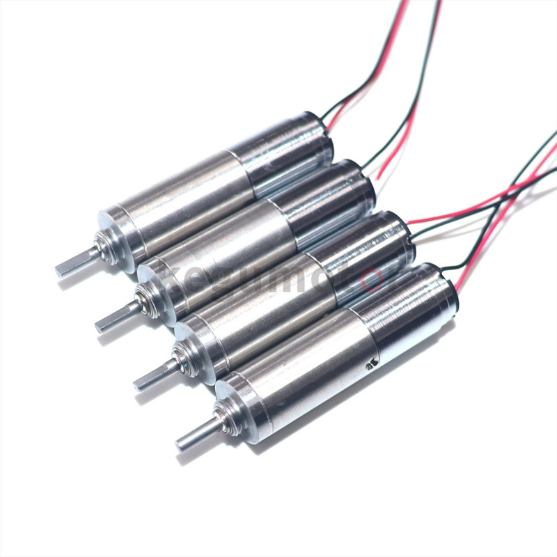
The 10mm brushless coreless motor mainly consists of four parts: a coreless rotor, a permanent magnet stator, precision bearings, and an electronic commutation system. Its structural characteristics differ fundamentally from traditional motors:
• Coreless Rotor: The core innovative structure uses self-supporting enameled wire wound into a hollow cup shape, without iron core laminations. The rotor mass is only about 1/10 of that of a similarly sized iron-core motor, resulting in extremely low rotational inertia (typically <5×10⁻⁷ kg·m²), achieving millisecond-level response. The windings are three-dimensionally precision wound, with precise matching of the number of turns and wire diameter, balancing conductivity and structural strength.
• Permanent Magnet Stator: Employs sintered neodymium iron boron (NdFeB) magnets (commonly N52 high grade), arranged in the stator housing using a radial multi-pole magnetization process to provide a stable air gap magnetic field; the air gap size is controlled between 0.2~0.3mm, balancing magnetic flux density and assembly precision.
• Precision Bearings: Utilizes miniature ball bearings or ceramic hybrid bearings to reduce friction loss, improve high-speed operation stability and service life, and keep noise levels below 40dB.
• Electronic Commutation System: Integrates Hall effect sensors (or a position detection module) and a driver chip (such as the TI DRV8305), replacing traditional mechanical brushes with electronic commutation to achieve forward and reverse rotation, speed regulation, and overload protection, extending motor life to over 10,000 hours.
2.2 Working Principle
The 10mm brushless coreless motor works synergistically based on the law of electromagnetic induction and electronic commutation technology: the stator permanent magnet generates a constant magnetic field, and the electronic commutation system applies alternating current to the three-phase coreless windings in a six-phase conduction sequence according to the rotor position signal, generating a rotating magnetic field; the rotating magnetic field interacts with the rotor permanent magnet magnetic field, driving the coreless rotor to rotate. Because the rotor has no iron core, there is no iron loss or eddy current loss, resulting in significantly higher energy conversion efficiency than traditional iron-core motors; simultaneously, the absence of cogging effect makes torque output smoother, with no jitter at low speeds, making it suitable for precision positioning scenarios.
III. Electromagnetic Design of the 10mm Brushless Coreless Motor
3.1 Design Objectives and Key Parameters
Based on the application scenarios of the 10mm micro motor, the core design objectives are determined as follows: diameter ≤ 10mm, length 20~30mm, rated voltage 3~12V, rated power 1~5W, no-load speed 10000~30000r/min, maximum torque 50~100mN·m, and efficiency ≥75%. Key parameters are selected as follows:
• Winding parameters: Enamelled wire diameter 0.05~0.1mm, number of turns 150~300, star three-phase connection, winding resistance controlled at 5~15Ω, inductance <10mH.
• Permanent magnet parameters: Neodymium iron boron magnet with remanence Br≥1.4T, coercivity Hcb≥800kA/m, magnetization method is radial multi-pole magnetization (2~4 poles).
• Air gap parameters: Air gap length 0.25mm, air gap magnetic flux density ≥0.6T, ensuring torque output and efficiency meet standards.
3.2 Electromagnetic Modeling and Simulation
A 3D electromagnetic simulation model of a 10mm brushless coreless motor was established using ANSYS Maxwell software. The core modeling steps are as follows:
1. Geometric Modeling: Based on design parameters, 3D solid models of the stator, coreless rotor, air gap, and bearings were constructed. Emphasis was placed on accurately depicting the cup-shaped structure of the coreless winding and the radial magnetization direction of the permanent magnets. The winding modeling adopted a user-defined Primitive method to ensure that the geometric parameters were consistent with the actual winding.
2. Mesh Generation: Mesh refinement was performed on key areas such as the air gap and windings, with a mesh size ≤0.05mm to ensure simulation accuracy. Unstructured meshes were used for the stator permanent magnets and rotor windings, with the total number of meshes controlled between 500,000 and 800,000 to balance computational efficiency and accuracy.
3. Boundary Conditions and Excitation Settings: The stator permanent magnets were set to radial magnetization, and remanence and coercivity parameters were set. Sinusoidal current excitation was applied to the three-phase windings, with the current amplitude calculated based on the rated power. Boundary conditions were set to far-field boundaries to simulate the actual electromagnetic environment.
4. Simulation Analysis: The simulation focuses on calculating core performance indicators such as air gap magnetic field distribution, electromagnetic torque, back electromotive force, and temperature rise. Simulation results show that the air gap magnetic field distribution is uniform, with magnetic flux density fluctuation <5%; the electromagnetic torque is stable under rated load, with a torque constant Kt of 1.5~2.5 mN·m/A, and the temperature rise ≤30K (after 1 hour of operation under rated conditions).
3.3 Electromagnetic Optimization Strategy
To address the issues of uneven local magnetic flux density and high copper loss discovered in the simulation, three optimization measures were implemented:
• Optimize winding method: Use skewed winding coils (Faulhaber process) instead of traditional straight winding, increasing the winding fill factor (from 60% to over 70%), reducing copper loss, and increasing power density.
• Adjust permanent magnet parameters: Select high-grade neodymium iron boron (N52SH) to improve remanence and temperature stability, while optimizing the magnet thickness (from 0.8mm to 1.0mm) to increase air gap magnetic flux density and improve torque output.
• Optimized Air Gap Length: Through precision assembly processes, the air gap length is optimized from 0.3mm to 0.22mm, increasing the air gap magnetic flux density by 10%~15% and torque density by 8%~12% while ensuring assembly feasibility.
IV. Manufacturing Process of 10mm Brushless Hollow Cup Motor
4.1 Core Manufacturing Process
The core challenge in manufacturing the 10mm brushless hollow cup motor lies in the hollow cup winding forming and precision assembly, requiring specialized equipment and high-precision process control:
1. Hollow Cup Winding Preparation: A multi-axis linkage laser positioning winding machine is used for precision winding of enameled wire, achieving a winding accuracy of ±0.005mm. After winding, vacuum impregnation (using 155℃ temperature-resistant insulating varnish) is performed to improve the winding structural strength and insulation performance. After impregnation, curing is carried out at 60~80℃ for 4~6 hours.
2. Permanent Magnet Preparation and Magnetization: Neodymium iron boron magnets are cut, ground, and polished, with outer and inner diameter tolerances controlled within ±0.01mm and coaxiality ≤0.01mm. A specialized multi-pole radial magnetization fixture is used for magnetization, ensuring a magnetization uniformity error of <3% and a stable magnetic field distribution.
3. Rotor Assembly: The formed hollow cup windings are bonded to the rotor support with epoxy resin. After assembly, dynamic balancing is performed for testing and correction, achieving a dynamic balancing accuracy of G1 level to prevent vibration and noise during high-speed operation.
4. Final Assembly and Debugging: The rotor, stator, bearings, and electronic commutation module are precisely assembled, controlling the coaxiality and clearance of each component. After assembly, initial power-on debugging is performed, checking the winding insulation resistance (≥20MΩ) and the accuracy of the commutation signal to ensure the motor operates without jamming or abnormal noise.
4.2 Process Quality Control
To ensure the dimensional accuracy and performance consistency requirements of the 10mm micro motor, a comprehensive quality control system was established:
• Raw Material Control: Permanent magnets are tested for parameters such as residual magnetism and coercivity, with a pass rate ≥99%; enameled wire is tested for diameter tolerance, temperature resistance rating, and insulation performance to ensure compliance with design requirements.
• Process Precision Control: Key processes such as winding, magnet grinding, and bearing assembly utilize laser inspection, with dimensional errors ≤0.01mm; the dynamic balancing process uses a high-precision dynamic balancing machine, with a correction amount ≤0.1g·mm.
• Finished Product Inspection: Inspection items include no-load speed, rated torque, efficiency, noise, temperature rise, and lifespan, with a finished product pass rate ≥90%, including efficiency ≥75%, noise ≤40dB, and lifespan ≥10,000 hours.
V. Control Strategy for a 10mm Brushless Coreless Motor
5.1 Drive System Hardware Design
The 10mm brushless coreless motor drive system is based on an STM32F429 microcontroller, combined with an H-bridge drive module (such as DRV8833), a current sampling module, and a Hall position feedback module:
• Power Drive Module: Employs low on-resistance MOSFETs (Rds(on)≤10mΩ) to reduce switching losses and improve drive efficiency; a 10μF ceramic capacitor + 100nF decoupling capacitor are connected in parallel at the H-bridge power supply to absorb transient current and suppress voltage fluctuations.
• Current Sampling Module: Uses a 0.1Ω precision sampling resistor paired with an INA240 current sensing chip to achieve current detection within a 0~5A range, with a sampling accuracy of ±1%, providing feedback for current loop control.
• Position Feedback Module: Integrates a miniature Hall sensor (or a 16-bit magnetic encoder) to acquire rotor position signals in real time, with a position detection accuracy ≤0.1°, ensuring accurate electronic commutation.
5.2 Closed-Loop Control Algorithm
A three-loop closed-loop control strategy—current loop, speed loop, and position loop—is adopted to suit the low inertia and high response characteristics of a 10mm brushless coreless motor:
1. Current Loop (Inner Layer): Using the sampled current value as feedback, a PI algorithm is employed to quickly suppress current fluctuations and stabilize torque output. Considering the motor's low inductance and fast current response, the proportional coefficient Kp is set to 0.5~1.2, and the integral coefficient Ki is set to 0.1~0.3 to avoid integral saturation.
2. Speed Loop (Middle Layer): Using the error between the speed feedback value and the target speed as input, a PI algorithm is used to adjust the current loop setpoint to achieve stable speed control. For high-speed operation scenarios, speed feedforward compensation is introduced to improve dynamic response speed, with overshoot controlled within 5%.
3. Position Loop (Outer Layer): Using the error between the position feedback value and the target position as input, a PD algorithm (avoiding integral saturation) is used to adjust the speed loop setpoint to achieve precise positioning. Position control accuracy can reach ±0.01°, meeting the positioning requirements of robot joints and medical equipment. 5.3 Anti-interference and Protection Design
To address electromagnetic interference and abnormal operating conditions during micro-motor operation, multiple protection mechanisms are designed:
• Electromagnetic Interference Suppression: A parallel RC absorption circuit (100Ω + 10nF) is connected at the motor end to suppress commutation spikes; the encoder signal uses shielded twisted-pair cable for transmission, and a 120Ω terminating resistor is added when the length exceeds 15cm.
• Abnormal Protection: Overcurrent protection (threshold is 1.5 times the rated current), overvoltage protection (threshold is 1.2 times the rated voltage), and overheat protection (temperature threshold 80℃) are designed. Upon triggering, the drive signal is immediately cut off to ensure safe motor operation.
VI. Experimental Verification and Result Analysis
6.1 Experimental Platform Construction
A performance testing platform for a 10mm brushless coreless motor is constructed. Core equipment includes: a DC regulated power supply (0~30V/5A), a dynamic torque sensor (accuracy ±0.1mN·m), a speed tester, a temperature rise tester, a noise tester, and an oscilloscope. The experiment included no-load characteristic testing, rated load characteristic testing, efficiency testing, response characteristic testing, and lifespan testing, simulating actual application conditions for verification.
6.2 Experimental Results and Analysis
1. No-load characteristics: At a rated voltage of 6V, the motor's no-load speed was 28000 r/min, the no-load current was 0.08A, and the no-load noise was 38dB, meeting the design requirements. The no-load back EMF waveform was close to a sine wave with a distortion rate of <5%, indicating a uniform magnetic field distribution.
2. Rated load characteristics: At a rated load of 50mN·m, the motor speed stabilized at 15000 r/min, the rated current was 0.8A, the efficiency reached 82%, the temperature rise was 25K (after 1 hour of operation), and the torque fluctuation was 1.8%, meeting the stability requirements of precision drive.
3. Response Characteristics: The motor accelerates from a standstill to 10,000 r/min in 12 ms and decelerates to a standstill in 8 ms. The calculated moment of inertia is 4.2 × 10⁻⁷ kg·m², 91% lower than that of a similarly sized iron-core motor, demonstrating excellent dynamic response performance.
4. Lifespan Test: After 1000 hours of continuous operation, the motor speed decreases by less than 3%, noise does not increase significantly, insulation resistance remains ≥15 MΩ, the electronic commutation module operates stably, and the lifespan reaches 12,000 hours, exceeding the design target.
Comparison of experimental results with simulation data shows that the error in core performance indicators is less than 10%, verifying the rationality of the electromagnetic design and manufacturing process. The developed 10mm brushless hollow cup motor outperforms traditional micro motors in efficiency, response speed, and operational stability, making it suitable for high-end precision applications such as robot dexterity hands, endoscope drives, and portable gimbals.
VII. Discussion and Technical Outlook
7.1 Analysis of Technical Challenges
The engineering application of 10mm brushless coreless motors still faces three major technical challenges: First, the manufacturing process of the coreless winding is complex, and high-precision multi-axis winding equipment relies on imports. Domestic mass production yield is only around 70%, restricting large-scale application. Second, the compact structure leads to heat dissipation difficulties; prolonged high-current operation easily causes excessive temperature rise, affecting motor lifespan and stability. Third, the machining precision requirements for miniature bearings and magnets are extremely high; dimensional errors easily lead to uneven air gaps, causing torque fluctuations and increased noise.
7.2 Directions for Technical Optimization
To address the above challenges, subsequent optimization research can be carried out in three aspects: First, develop domestically produced high-precision coreless winding equipment, adopting multi-axis linkage laser welding technology to improve winding forming accuracy and mass production yield. Second, integrate miniature heat dissipation structures (such as aluminum substrates and miniature heat pipes), combined with temperature rise prediction models, to dynamically limit the operating current and solve the heat dissipation problem. Third, optimize the assembly process of magnets and bearings, using precision tooling to ensure...

 ∷
∷

 Engineer 1
 Engineer 2